3D Printed Kinematic Mirror Mounts
The following is a guide on how to fabricate a low-cost alternative to commercial mirror mounts (around $40 at their cheapest). Additionally, these allow you to customize your optics holder for any shape and size of optical element, which I found particularly useful as I was buying random surplus off of eBay. As a disclaimer, these mounts will have more thermal drift than anything commercial, and thus are less suitable for long-term experiments.
Theory
Kinematic mirror mounts are optomechanical devices ubiquitous in optical systems as they provide the ability to precisely tune the direction of a laser beam. This is achieved through the use of kinematic couplings, from which these devices get their name.
The kinematic coupling fixtures constrain a baseplate and optics holder to be aligned in a fixed and highly repeatable manner, by ensuring that there are exactly six points of contact between the two (restricting the six mutual degrees of freedom between them). The method of affixing the baseplate and optics holder together is typically either via extension springs (most common) or magnets (but never bolts, as this would defeat the purpose of having only six points of contact).
The six points of contact in a kinematic mirror mount are given by three round-tip screws through the baseplate that contact grooves in the optics holder. As the screws are driven, they push against one side of the optics holder, forcing it to tilt slightly in that direction. Thus, if the optics holder is holding a mirror with a laser beam incident on it, the output beam directionality will shift correspondingly. The springs holding the two pieces together provide a restoring force to un-tilt the optics holder if the screw is loosened.
Fabrication
Tools Required
- SLA 3D Printer (FDM possible but not recommended)
- Scotch Tape
- Epoxy
Bill of Materials
Purchase
- M4 or 6-32 Bushings x 3 (~$0.10 x 3)
- M4 Ball-Tip Screws x 3 (~$0.50 x 3)
- 1.5mm diameter, 6mm length dowel pins x 6 (~$0.25 x 6)
- 0.125in diameter, 0.5in length extension springs x 3 (~$0.80 x 3)
- M3 bushing or nut (~$0.02)
Print/Machine
- Mirror Holder (modify this to your mirror dimensions)
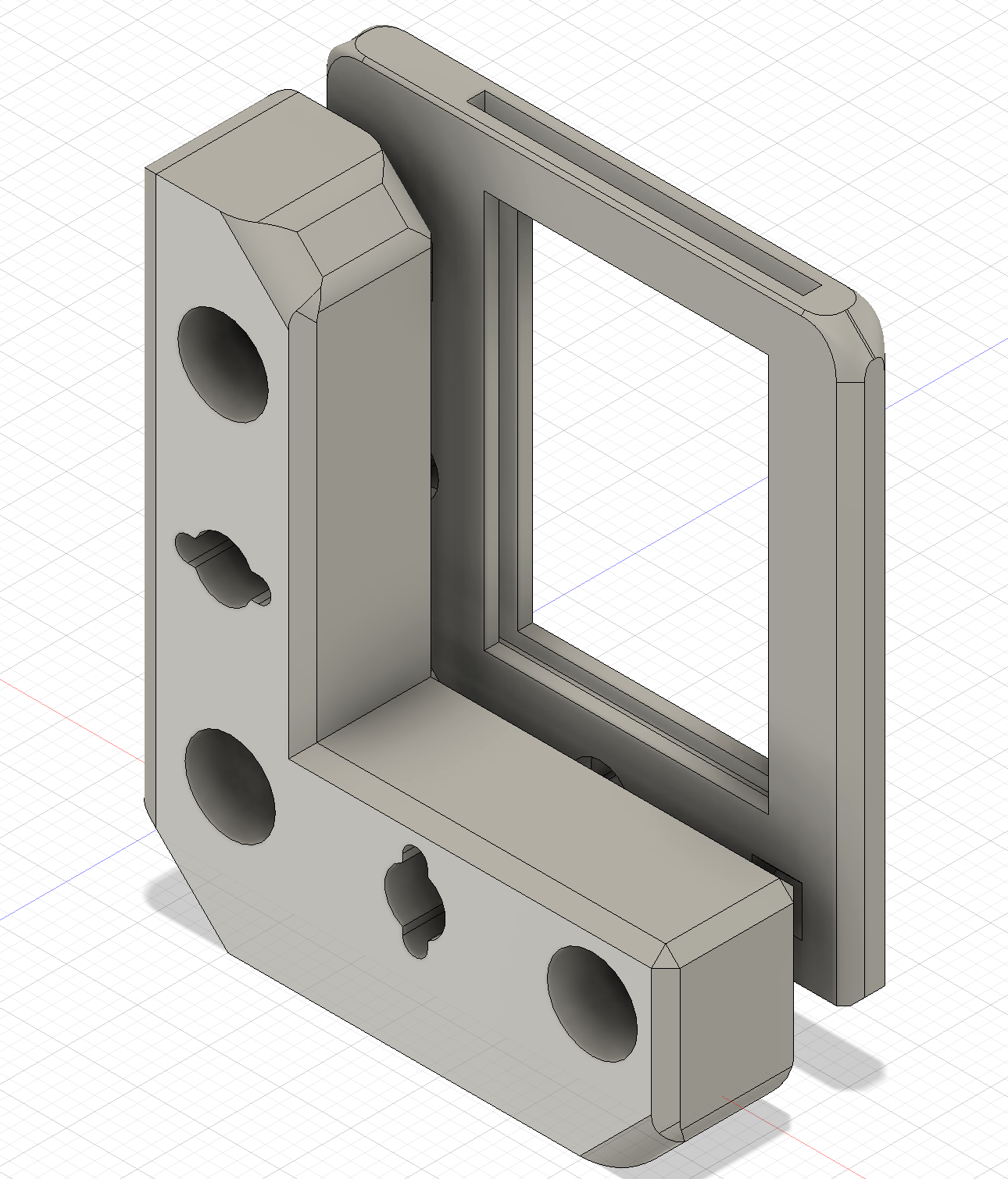
- Kinematic Mount (modify the bushing holes to your bushing dimensions)
Assembly
I salvaged mirrors from a broken LCD projector (which, as an aside, is a great source of mirrors, prisms, lenses, and dichroics!), hence the random dimensions of 26x20mm. The mirror should slot into the mirror holder tightly enough to provide a tension fit to prevent any unwanted mechanical disturbance (you can modify the design to include a tension screw, or you can epoxy the mirror in, for extra sturdiness).
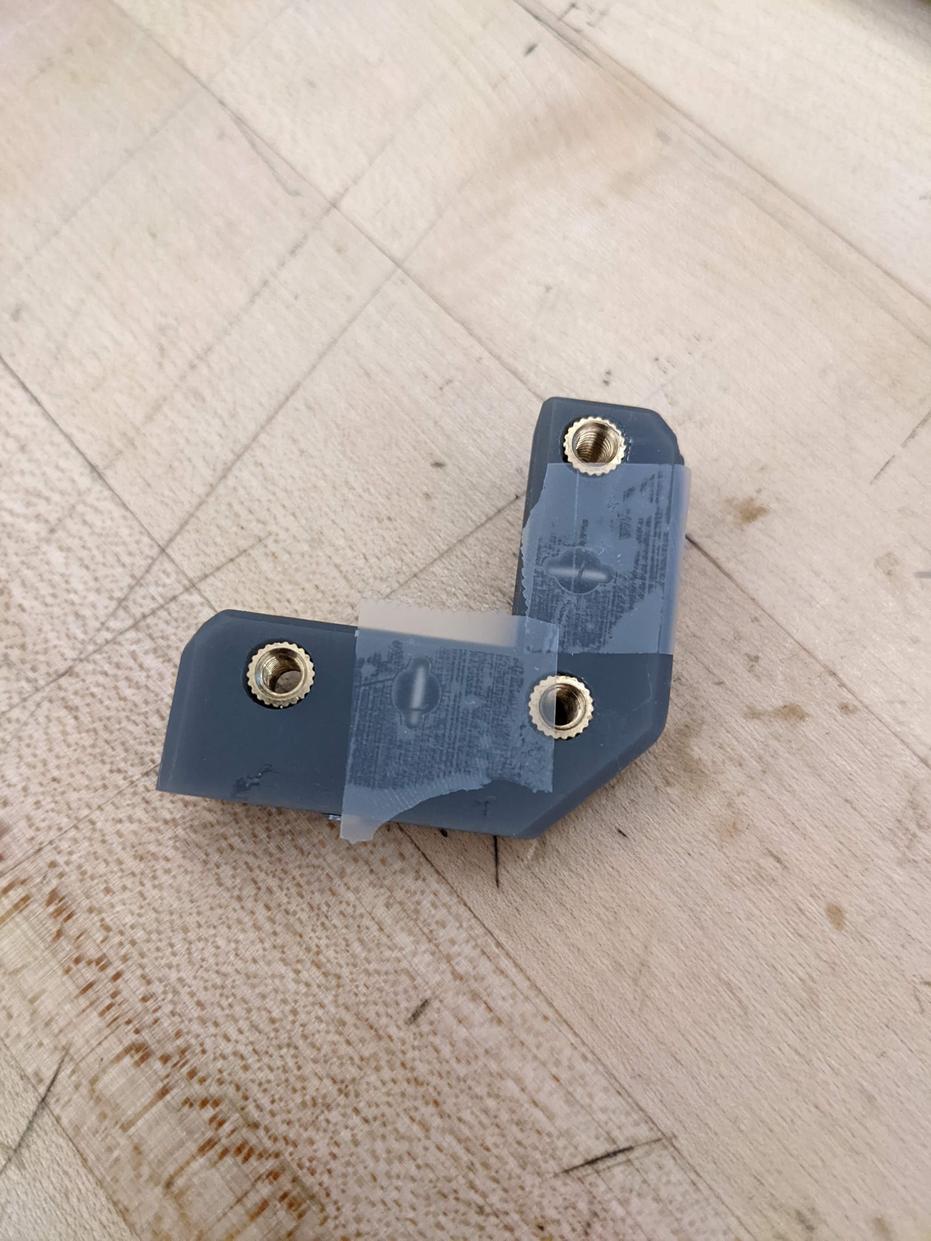
Next, epoxy your bushings into the holes in the kinematic mount. I used three M4 bushings for the adjustment screw holes, and an M3 bushing for the set screw hole to mount onto an optics post.
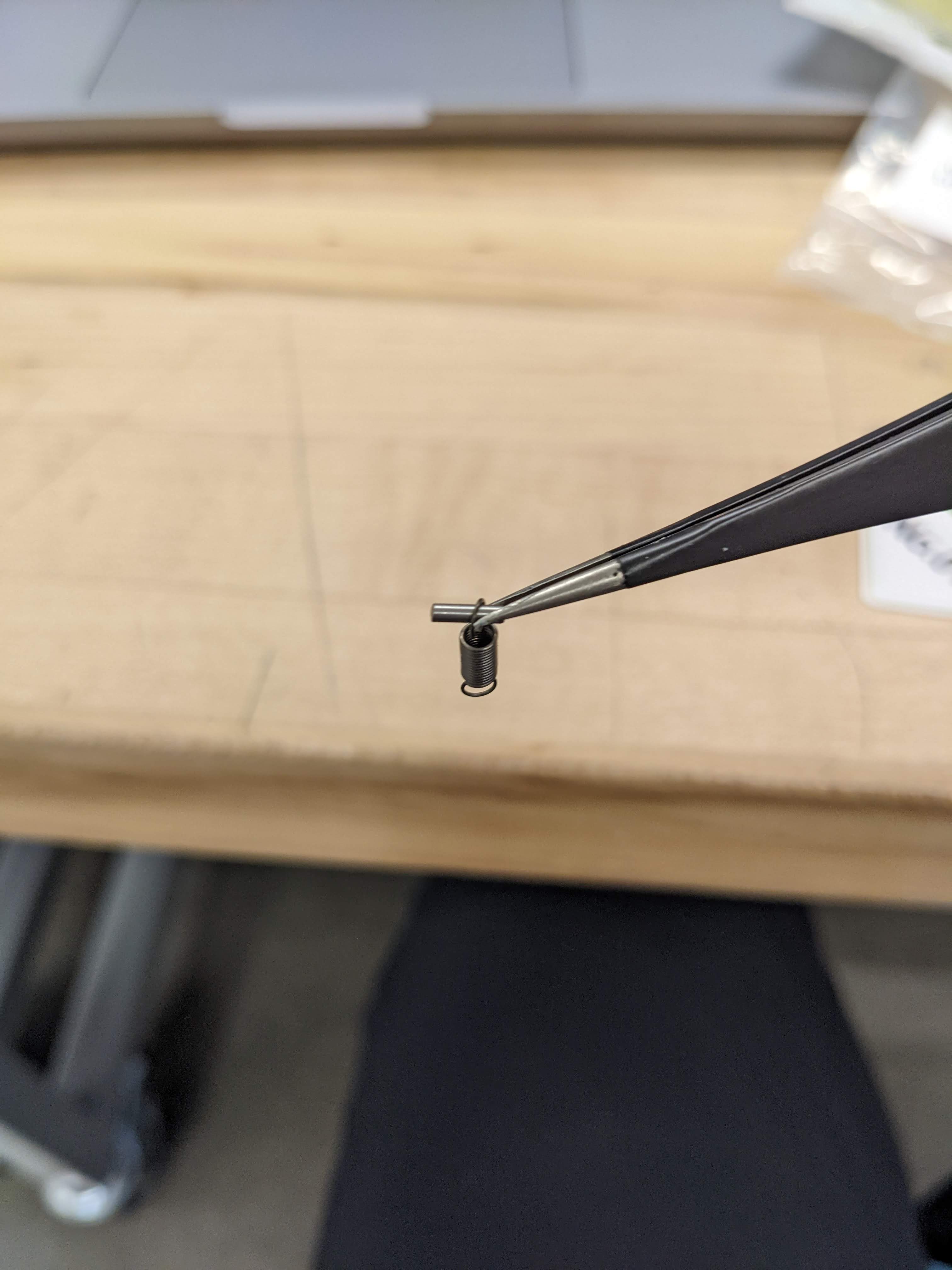
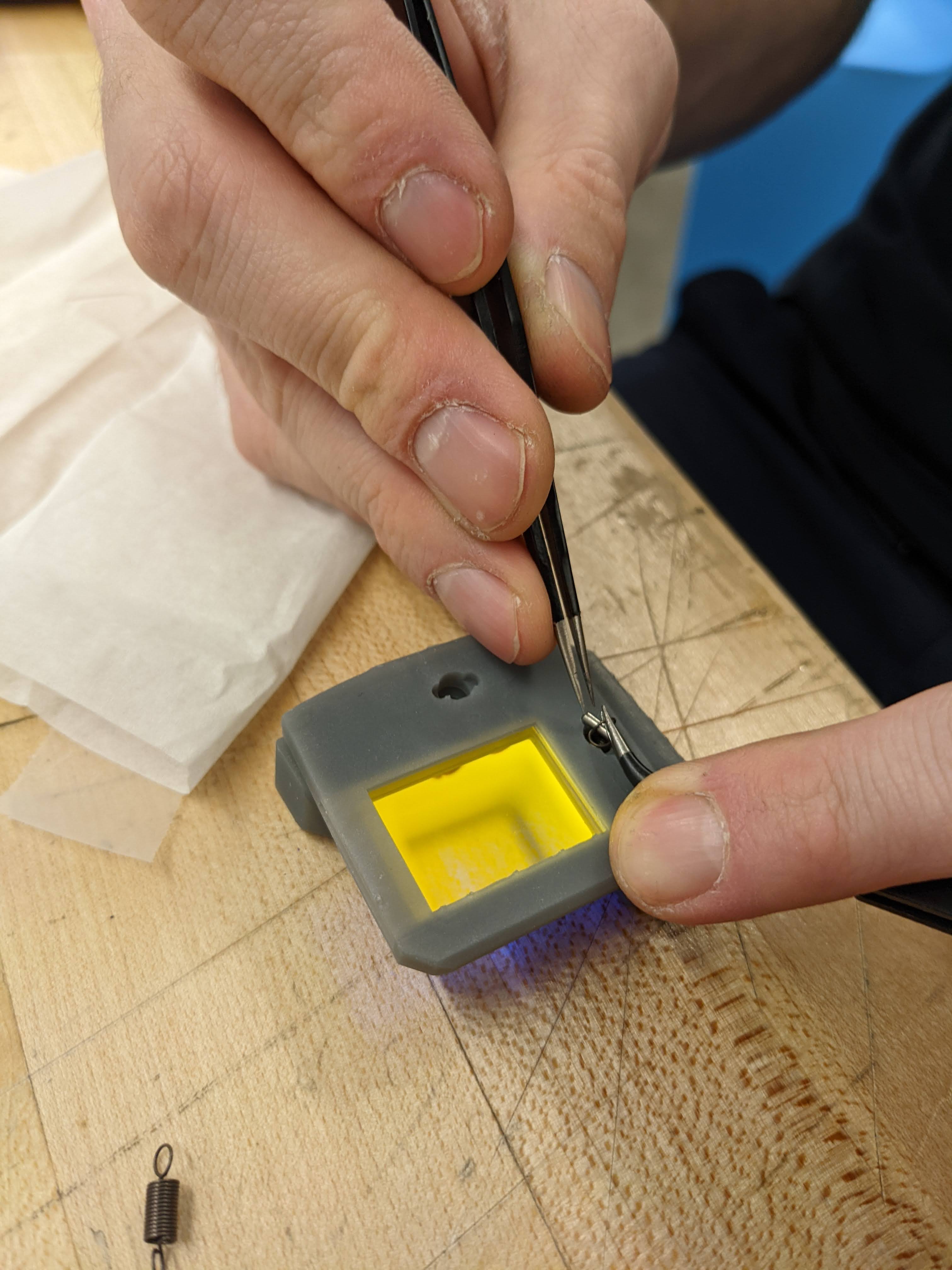
Then, thread a steel dowel pin through one of the loops on the end of a spring. Drop the dowel pin (with the spring attached) through the smaller hole in the kinematic mount, so that the dowel pin sits in the rectangular inset in the mount. Place a piece of scotch tape over the inset, so that the dowel pin and spring do not fall out. Do this for both insets. Then, flip the mirror mount over, and lift up the spring loop with a pair of tweezers. Use a second pair of tweezers to pick up another dowel pin and slide it through the spring loop. Do this for both spring slots, and then scotch tape over these holes as well.
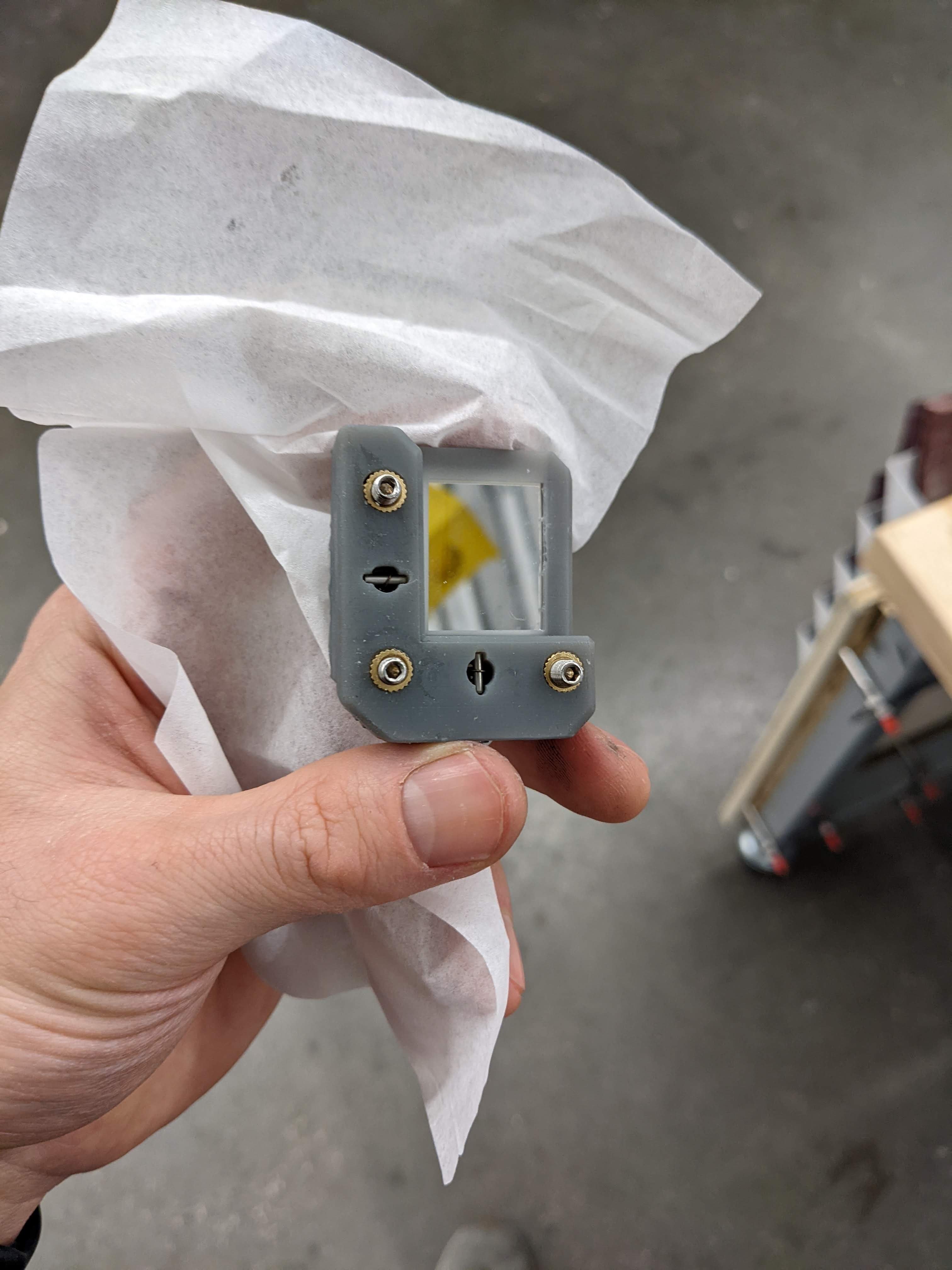
The final step is to screw your M4 ball-tip screws into the bushings until they sit in the triangular mounting insets in the mirror holder. Drive the screws far enough so that the springs are under tension, and the dowel pins will not fall out on their own. Then, the scotch tape can be removed, the mirror mount is fully assembled.